The IMAGE observatory is scheduled for launch in January 2000 from the Western Range (WR). The observatory will be placed in a highly elliptical orbit of 1000 km by 7 Earth radii (Re). The IMAGE mission is designed to use simple and repetitive ground operations once the science collecting phase is entered. The observatory will operate nearly autonomously throughout its science collecting phase. Control of housekeeping and science collecting functions is provided on-board the observatory. During the science collecting phase of the mission, one to two telemetry passes per day and one command load per week will be sufficient to support operations.
Following the launch and deployment phase, the Attitude Control System (ACS) operates in a single mode, maintaining a constant spin rate of the observatory. Although the scientific payload is composed of seven individual science instruments, the on-orbit science operations require minimal input from the ground. The instruments operate in a nearly constant mode. Instruments requiring occasional calibration operations and safing measures to avoid sun-pointing constraints are supported through the normal weekly command loads.
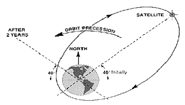
The observatory does not have a propulsion system. Following insertion into the mission orbit by the launch vehicle, the observatory's orbit will vary under natural forces only. The predicted variation of the orbit over the two year mission lifetime will be advantageous to meeting the science objectives.
The SMOC serving the IMAGE mission will be located in Building 3 at the GSFC. The SMOC will contain the necessary ground system components, both hardware and software, to manage all routine observatory operations and process the science data. Information transfer between the SMOC and the scientific investigation team will be supported by communications using the Internet and WWW.
MISSION PHASES
Pre-Launch: Includes I&T activities up to disconnect of the umbilical lines.
Launch/Ascent: Flight required to establish the mission operations orbit.
Initialization and Checkout: Spacecraft and instrument checkout and deployment. This phase may require up to 41 days.
Mission Operations: Normal science data collection mode.
Deactivation: Following the completion of the science collection phase, spacecraft operations will be terminated. No means for changing the orbit or performing a controlled re-entry are provided.
NORMAL OPERATIONS
During normal operations the observatory will collect science data in a nearly continuous and autonomous mode. The SMOC will receive weekly science inputs from the PI located at the SwRI. These inputs will be a compilation of the science team members' requests, including commands to the science instruments, scheduling inputs, and science data processing instructions. The SMOC will be responsible for verifying and integrating the science instrument commands into the weekly command loads.
The JPL/DSN will provide the telecommunications link between the observatory and the IMAGE ground system. 34 meter antennas will be used to provide the necessary RF link margin. One to two passes per day will be required to dump the Bulk Memory Recorder on-board the observatory. Command loads will be transmitted to the DSN once per week for uplink to the spacecraft. Telemetry downlink rates of 2,285,700 bps and 44,000 bps and a command uplink rate of 2.0 kbps will be used.
The SMOC will process both housekeeping and science data. Real-time (R/T) data is monitored for both spacecraft and science instrument health and status. Dumped housekeeping data will be processed to verify the spacecraft's performance through the generation of trend reports. The SMOC will perform low level processing and distribution of science data, including any ancillary data needed for the interpretation of the science data.
The design of the IMAGE mission in both the ground and space segments lends itself to the use of automation in the performance of normal on-orbit operations. The SMOC operations system will be capable of performing routine operations concerning data acquisition and processing, generated command load uplink, and notification of a designated SCT member in the event that a non-nominal condition is detected. These built-in functions will enable the mission goals to be achieved with a small SCT staffing the SMOC eight hours per day, five days per week during the normal mission mode.
SUPPORTING ELEMENTS
The SwRI will direct the science operations through the generation of schedules, and provide the SMOC with consolidated sets of instrument commands from the instrument team. IMAGE co-investigators will participate from their respective facilities via the Internet and the WWW.
The SMOC will perform both science and mission operations. The SMOC will be responsible for the safe and successful operation of the spacecraft, generating and verifying command loads, monitoring the spacecraft health and safety, and scheduling all necessary support services. The SMOC will receive and decommutate spacecraft telemetry, perform Level-0 processing, generate science products, and provide data distribution.
The SMOC will generate all orbit-related products required for on-orbit operations and science data processing. Support by the Flight Dynamics Facility (FDF) at GSFC will be required.
The JPL/DSN will provide the RF link to the spacecraft for command, telemetry, and radio metric services. Additionally, the DSN will provide short term storage of recorded downlinked data in case retransmission to the SMOC is required.
The National Space Science Data Center (NSSDC) will provide science data archiving and distribution functions.
The NASA Integrated Services Network (NISN) will provide the communications links between the various ground system elements.

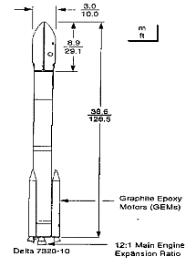
Figure 1000-2 shows the Delta 7320 family of vehicles.

Figure 1000-2: Delta 7320 Family
The ACS will be capable of maintaining the spin axis alignment to within 1.0 degree of the vector normal to the orbit plane. The spin axis attitude and the spin phase will each be determinable to within 0.1 degree and are calculated on-board the spacecraft. The sensors include a Three Axis Magnetometer (TAM) and an Autonomous Star Tracker (AST). The actuators include a single torque rod and a nutation/spin rate damper. Body mounted solar arrays provide the primary source of power outside of eclipse periods. Solar array panels will be mounted around the radial surface and on both ends of the observatory’s cylindrical body. A battery will provide support during launch operations and seasonal eclipse periods experienced near the equinoxes. The size of the battery will be sufficient to allow normal science operations to continue during eclipse periods.
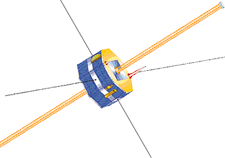
Figure 1000-3 shows the IMAGE spacecraft.

Figure 1000-3: IMAGE Spacecraft
The IMAGE spacecraft will have one Medium Gain (Helix) Antenna with the following specifications:
b. Gain: 3.4 dBi (min, at half-power beamwidth), 6.4 dBi peak
c. Polarization: RH Circular
d. Pattern: toroidal, 360 degrees by +-7.2 degrees normal to spacecraft spin axis.
The IMAGE spacecraft will also have a Low-Gain (Omni) Antenna Pair with the following specifications:
b. Gain (pair): = 0 dBi from 0 degrees to +-70 degrees and +-140 degrees to 180 degrees; and -25 dBi from >+-70 degrees to >+-140 degrees relative to the spacecraft spin-axis, not including interferometer nulls.
c. Pattern (pair): Hemispherical with near spherical usability (not including spacecraft and interferometer effects). The deepest nulls shall be no greater than -50 dBi.
d. Gain LGA-1 Alone: 0 dBi from 0 degrees to +-90 degrees; = -4 dBi to +-120 degrees; = -10 dBi to +-140 degrees; trailing off to -35 dBi at +-180 degrees from the +Z-axis, excluding spacecraft interference effects.
The IMAGE spacecraft will have the following RF Control Devices:
MGA/Omni Antenna Selection Switch
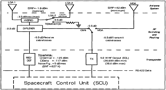
A single-pole, double-throw (SPDT) RF coaxial switch is used to allow transmitting on either the medium gain or the low gain antenna. Since this latching switch remains in the last selected position, an explicit command is required to change from normal operations, which is transmitting over the medium gain antenna, to transmit via the low gain antenna(s). The receiver is always connected to the low gain antenna(s).
Omni Antenna Selection Switch
A SPDT RF coaxial switch is used to disconnect the LGA 2 (-Z axis) antenna from the power combiner/splitter during normal operations, thereby eliminating the problem of severe interference nulls on the uplink. During initial acquisition, check-out, and safe-mode operation, inputs from the two omnis are combined to provide near 4 pi steradian coverage. Since this switch is latching, an explicit command is required to change from normal operations using the + Z low gain antenna (LGA 1) to operating with both the +Z and -Z low gain antennas (LGA 1 and LGA 2).
Diplexer
A diplexer is added to the low gain antenna circuit to allow simultaneous receive and transmit capability. The medium gain antenna is used only for transmit. The low gain antenna is always used for receive, but can also be used for transmit, if necessary.
Power Combiner/Splitter (Hybrid)
The Power Combiner/Splitter is necessary to enable simultaneous use of the two low gain antennas for hemispherical coverage. This does not allow a "perfect" 4 pi steradian coverage due to the interferometer effects between the two antennas. For this reason, only one low gain antenna (LGA-1) is used during normal operations.
SPACECRAFT CONTROL UNIT (SCU)
The SCU interfaces with the communications subsystem and performs the normal Command and Data Handling functions.
Figure 1000-4 shows the IMAGE Communications Subsystem.

Figure 1000-4: IMAGE Communications Subsystem
Author and Curator:
Dr. D.R. Williams, dwilliam@nssdc.gsfc.nasa.gov, +1-301-286-1258