The IMAGE spacecraft provides an uplink and downlink communication capability which is compatible with the DSN 34 m and 26 m stations.
The IMAGE uplink rate is 2000 bps. The IMAGE downlink rates are 2,285,700 bps, and 44,000 bps.
All communication formats and frequencies are specified in Section 2000.
Downlink: Normally, IMAGE will make one (1) telemetry transmission per orbit. The telemetry rates are selectable depending on the phase of the mission. In all downlink formats/rates, Reed-Solomon error correction coding is added. The telemetry data is phase modulated directly onto the S-band downlink carrier.
Upon receipt by DSN, the telemetry is demodulated, recorded, and transmitted to the SMOC.
Table 1000-2: IMAGE Transponder Transmitter and Telemetry Link Characteristics
| PARAMETER | VALUE |
| a. RF Output Power | 5.0 Watts |
| b. Transmit Frequency (S-Band) | 2272.500 MHz |
| c. Coherent Turnaround Ratio | 240/221 |
| d. Frequency Stability | 30 ppm (non-coherent) |
| e. Direct Carrier Modulation Rate | 2.5 Mbps BPSK |
| f. Linear Phase Modulation | 1.3 radians |
| g. Ranging | SRA with 0.33 m.i. |
| h. Coding | PN & R/S |
| i. Sub-carrier Frequency Selected | *1.7 MHz |
| j. Sub-carrier Type | *Filtered Sq. Wave |
| k. Sub-carrier Stability | *+/-0.005% |
| l. Sub-carrier Modulation | *BPSK |
| m. Sub-carrier Mod Index | *1.3 radians |
| n. Sub-carrier Data Rate | * 64 kbps |
| o. Telemetered Monitors | Temp.; RF Pwr. Out; DC Converter Voltage |
| p. Commands Accepted | Transmitter Power ON/OFF; SCO ON/OFF; Coherent Mode ON/Off; Ranging ON/OFF |
Command operations will include both real-time commanding and stored command loads uplinked to the spacecraft via DSN (real time) throughput commanding service. Real-time commanding is the uplink of commands or data intended for immediate implementation/use by onboard systems. Real-time commanding enables the immediate verification of command reception through the COP-1 protocol, as well as the verification of command implementation through telemetry of affected system parameters. Stored command loads consist of absolute and relative time based command data files. These commands and data are stored in the onboard memory and are intended for future use by onboard systems. Stored command loads direct and provide necessary data for the onboard processors to perform autonomous operations between ground contacts. The reception of stored command load data by the spacecraft is provided through the COP-1 protocol.
For all mission phases, real-time commanding is required during DSN contact periods. During nominal operations the frequency of stored command loads will normally be one load per week. All stored command loads performed will occur within the normal pass time frame; stored command loads do not affect the duration of the daily pass period.
Stored command loads will primarily consist of commands associated with the pass operations schedule. These commands affect onboard configurations and operations required in support of the daily pass operations.
The IMAGE SMOC will format all commands (real-time and stored command load) and transmit them to the DSN for uplink to the spacecraft. Real-time commands will be generated by the SMOC and transmitted to the DSN at generation time for immediate uplink. The SMOC may format a command load and transmit the command load data as it is generated to the DSN for immediate uplink to the spacecraft.
Normally, a command uplink will occur once per week to load a schedule. The IMAGE SMOC will format the commands and transmit them to DSN for uplink to the spacecraft. Command data structure is based upon the CCSDS COP-1 recommendations.
Table 1000-3: IMAGE Transponder Receiver and Command Link Characteristics
b. Carrier Tracking Range: +- 140 kHz v c. Carrier Acquisition Threshold (sweep mode): -125 dBm
d. Carrier Tracking Threshold (sweep mode): -125 dBm
e. Maximum Carrier Loop Tracking Range: +-140 kHz at threshold (Tol. +10 kHz)
f. Acquisition Sweep Rate: 32 kHz/sec max (at threshold)
g. Acquisition Times: Uplink sweep: 15 sec max
h. Noise Figure: 5 dB max
i. Loop Noise Bandwidth (2 bL): 800 Hz fixed (non-expanding)
j. Dynamic Range: -40 dBm to threshold
k. Maximum input signal (carrier threshold): +3 dBm (Tracking Loop SNR = 0 dB)
l. AGC curve maximum input power limit: -50 dBm
m. Pre-selector Filter: 2 pole, 150 MHz
n. Pre-detection Bandwidth: 1.0 MHz
o. Spurious Response: >60 dB below desired response
p. Ranging Channel: PN Code with 0.5 Mod Index
q. Command Channel Bandwidth: 1.5 kHz to 1.2 MHz
r. Command Sub-carrier Frequency: 16 kHz
s. Command Data Rate: 2,000 bps
t. Command Threshold @10-6 BER: -118 dBm @ 2 kbps & 1 radian mod index
u. Telemetry Output: Signal Strength; Loop Stress; Converter Voltage; Carrier Lock/Demod Lock
Table 1000-4 contains the IMAGE communications commands.
Table 1000-4: Communications Subsystem Commands
| 1 | Transmitter Power | ON | 2 | Transmitter Power | OFF |
| 3 | Subcarrier Oscillator | ON | 4 | Subcarrier Oscillator | OFF |
| 5 | Coherent Mode | ON | 6 | Coherent Mode | OFF |
| 7 | Ranging | ON | 8 | Ranging | OFF |
| 9 | Convolutional Encoder | ON | 10 | Convolutional Encoder | OFF |
| 11 | Transmit Ant. Select | LGA | 12 | Transmit Ant. Select | MGA |
| 13 | Receive Ant. Select | LGA - 1&2 | 14 | Receive Ant. Select | LGA - 1 Only |
1431.3 The following is the Initial Acquisition Configuration:
| 1,3,5,7,10,11,13, and Receiver On (hard-wired) |
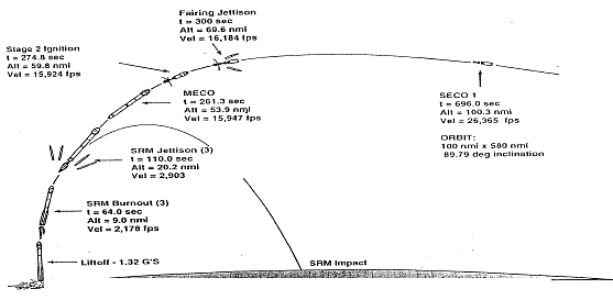
Figure 1000-5 shows spacecraft Launch to separation details.

Figure 1000-5: Delta 7325 IMAGE Mission Preliminary Boost Phase Profile
| Event | MET (seconds) |
| Liftoff | 0.0 |
| Mach 1 | 36.1 |
| Maximum dynamic pressure | 50.6 |
| Solid motor burnout(3) | 64.0 |
| Solid motor separation(3) | 110.0 |
| Main engine cutoff | 261.3 |
| Vernier engine cutoff | 267.3 |
| Stage 1/2 separation | 269.3 |
| Stage 2 ignition | 274.8 |
| Fairing separation | 300.0 |
| First stage 2 cutoff | 696.0 |
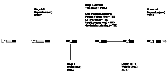
| Start stage 3 ignition time delay relay, Fire spin rockets | 3020.7 |
| Stage 2/3 separation | 3023.7 |
| Stage 3 ignition | 3060.7 |
| Stage 3 burnout | 3125.4 |
| Deploy Yo-Yo weights (despin stack) | 3270.7 |
| Spacecraft Separation | 3275.7 |

Figure 1000-6: Delta 7325 IMAGE Mission Preliminary Orbit Injection Profile
Table 1000-5 summarizes IMAGE operations.
Table 1000-5: IMAGE Operations Summary
|
|
|
|
|
|
|
|
|
|
|
|
|
|
|
|
|
|
|
|
|
|
|
|
|
|
Author and Curator:
Dr. D.R. Williams, dwilliam@nssdc.gsfc.nasa.gov, +1-301-286-1258