2. TECHNICAL APPROACH
The IMAGE mission will address its magnetospheric imaging objectives in unique ways using existing imaging techniques: neutral atom imaging (NAI) over an energy range from 10 eV to 200 keV, far ultraviolet imaging (FUV) at 121-160 nm, extreme ultraviolet imaging (EUV) at 30.4 nm, and radio plasma imaging (RPI) over the density range from 0.1 to 105 cm3 throughout the magnetosphere. Science objectives developed in the Step-1 proposal result in the instrument requirements listed in Table 2.1. A minimum baseline mission, below which IMAGE would not be worth pursuing at the proposed cost, has been identified to include two of the three NAI instruments (MENA and HENA), the EUV instrument, and one of the two FUV instruments (either the spectrographic imager or the wideband imaging camera). With this minimum complement, IMAGE would accomplish the complete set of science objectives that have been identified for the core Magnetosphere Imager mission [Armstrong and Johnson, 1995]. Details of the proposed descope process are contained in Volume II.
|
Imager |
Measurement |
Critical Measurement Requirements |
|---|---|---|
|
NAI |
Neutral atom composition and energy-resolved images over
three energy ranges: |
FOV: 90 x 90 degrees (image ring current at
apogee). |
|
EUV |
30.4 nm imaging of plasmasphere He+ column densities. |
FOV: 90 x 90 degrees (image plasmasphere from
apogee)., |
|
FUV |
Far ultraviolet imaging of the geocorona and the aurora at [[lambda]] = 134-160 nm (Wideband Imaging Camera, WIC) and [[lambda]] = 121.6, 130.4, and 135.6 nm (Spectrographic Imager, SI) |
FOV: 16 degree (image full Earth from apogee).
|
|
RPI |
Remote sensing of electron densities and magnetospheric boundary locations using radio sounding. |
Density range: 0.1-105 cm-3 (determine electron
density from inner plasmasphere to magnetopause). |
The IMAGE mission is designed to have very low risk because it uses (1) science instruments with a high level of technical readiness, with all subsystems having been either flight-proven or verified with extensive ground-based and laboratory testing; (2) a direct application of the FAST SMEX spacecraft; and (3) the existing Goddard Space Flight Center (GSFC) Science and Mission Operations Center (SMOC) with very simple on-orbit operations.
2.a. Mission Design
A full design study using an existing spacecraft architecture (FAST) was performed by GSFC (Code 700). This analysis concluded that an adapted FAST architecture with the instrument complement in Table 2.1. will meet all IMAGE requirements within the MIDEX cost and spacecraft resource limits. This mission design provides the highest possible science per unit cost by making extensive use of existing flight and ground systems, software, and procedures. Flight-proven hardware designs are used wherever possible, while laboratory-proven new technologies enhance the science return. Operational complexities such as stringent spacecraft pointing requirements and narrow launch and operational windows have been eliminated.
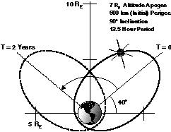
2.a.1. Orbital Requirements. A full analysis of the required IMAGE orbit has been performed by the GSFC Flight Dynamics Division. The orbital requirements for the IMAGE mission are shown in Fig. 2.a.1. The initial argument of perigee is 320 degrees, placing the initial apogee at 40 degrees north latitude. The apogee will drift to be over the north pole after one year and back to ~40 degrees north latitude at the end of the two-year mission. A 0 or 180 degrees right ascension of the ascending node (RAAN) places the spacecraft spin axis at 23.5 degrees to the ecliptic plane. This orientation minimizes the sun-angle variation, optimizing solar input to the body-mounted solar panels.
The basic Med-Lite launch vehicle (Orbital Sciences Corporation Taurus vehicle with a Star 37FM upper stage, two Castor IVB strap-on motors, and a 2.3-m fairing) will place a 373 kg payload into the required orbit. The IMAGE spacecraft mass of 291.5 kg provides a substantial mass margin of 81.5 kg. The Delta-Lite launch vehicle will also meet the IMAGE orbit requirements because it provides an even greater mass-to-orbit capability.
An orbit error analysis performed by McDonnell Douglas for IMAGE estimates 3 errors of 9 km on perigee and 1700 km on apogee. These small dispersions allow IMAGE to be placed into the required orbit without the need for an onboard propulsion system.
Fig. 2.a.1. The IMAGE orbit maximizes observation time over the north pole during the 2-year mission and provides ample ground station coverage. A downlink time of only 13.5 min./day is needed.
2.a.2. Launch and Operational Windows. The IMAGE spacecraft can be launched any day of the year to attain the required orbit. The launch window is constrained only by the time of day, with a minimum launch window of one hour per day. For communications there is ample ground station coverage for DSN northern hemisphere ground stations with contact times of about 8 hours per 13.5 hour orbit using a DSN 34-m antenna (see Fig. 2.a.1.). However, a downlink time of only 13.5 min/day is needed. The smaller 26-m DSN antenna also can be used owing to the considerable margin in the downlink window. This smaller DSN antenna will necessarily require a slower telemetry rate and a corresponding increase in the data downlink interval to ~25 minutes.
2.a.3. Mission Lifetime. IMAGE is a two-year mission (see Fig. 2.a.2.).
Fig. 2.a.2. Natural evolution of perigee altitude for the IMAGE mission results in the main mission being accomplished with perigees above 600 km, giving a safe margin of stability even for higher than expected solar activity.
2.a.4. Communication Requirements. The IMAGE data will be transmitted as packets in a store-and-dump mode except for real-time transmissions during launch and early orbit (when instrument and spacecraft checkout is performed). The telemetry rates and volumes will be sized to allow automated ground operations. The telemetry protocol and formats will follow the Consultative Committee for Space Data Systems (CCSDS) standards for cost-effective use of existing equipment. The DSN is the baseline tracking network. Schedulingof DSN will be relatively simple because of the short downlink time relative to the length of time the spacecraft will be visible to the DSN (see Fig. 2.a.1.).
Based on the IMAGE telemetry rate with 1.8:1 instrument data compression (Section 2.c.3.), a downlink rate of 2.2 Mb/s, and a DSN 34-m antenna, the data downlink time from the onboard solid-state memory is approximately 13.5 minutes per day (bit error rate 10-5). The 2.0 Gbit solid-state memory will have the ability to store two full orbits (27 hours) worth of data. All rates and times given include a 20% margin on total data.
2.a.5. Orbit Determination. Orbit determination will be performed once per orbit in the GSFC SMOC by the GSFC Flight Dynamics Division. Spacecraft position knowledge (above ~2 RE altitude) is required to within 50 km after the fact to determine the geographic location of individual pixels in the auroral images.
|
Spin Axis Direction |
< 10 degree perpendicular to the orbit plane |
|---|---|
|
Spin Axis Stability |
0.005 0 /s |
|
Attitude Knowledge (at apogee) |
0.1 0 spin angle |
|
Spin Rate (final) |
0.5 +/-0.1 rpm |
2.a.6. Attitude Determination. Spacecraft attitude determination will be performed on board by the IMAGE attitude control system (ACS) to within the accuracy and stability listed in Table 2.a.1. Attitude determination will also be performed on the ground using the FASTRAD system.
2.a.7. Spacecraft Pointing Requirements. Table 2.a.1. summarizes the IMAGE spacecraft pointing requirements. Once the spin axis is fixed, the RPI antennas are deployed, and the final spin rate is attained, no special spacecraft maneuvers are required.
2.a.8. Mission Operations (MO) Scenario. Launch and Early Orbit. After launch and vehicle separation, the ACS will align the spacecraft spin axis perpendicular to the orbit plane and maintain a spin rate of 0.5 rpm. Antenna deployment (identical to that of the FAST spacecraft) will occur in the Early Orbit phase (Figure 2.a.2.). During the ~25% of the orbit centered around perigee, the antennas are slowly deployed while two spin torque rods maintain the spin rate. A third torque rod negates spin rod precession and maintains the spin-axis attitude, and a fluid damper reduces spacecraft nutation. Analysis of the IMAGE spacecraft moment of inertia and perigee magnetic field indicates that the antennas will be fully deployed in ~40 days. This deployment period allows sufficient time for normal instrument high- voltage turn-on and check-out.
Main Mission. The main mission starts after the antennas are deployed (Figure 2.a.2.). Instruments will remain fully powered and will operate autonomously throughout this phase. Most instruments have only one science acquisition mode, and those that have more than one will still operate autonomously with occasional preprogrammed mode changes uplinked during data acquisition intervals. Only one contact per week will be required for spacecraft commanding. Instrument health and safety checks will be automated with data derived from the normal downlink.
2.b. Instrumentation
The IMAGE instrumentation is summarized in Table 2.1. above. The various imagers communicate with the spacecraft through a Central Instrument Data Processor (CIDP), making them appear as one instrument for command, data, and electrical power purposes.
|
|
LENA |
MENA |
HENA |
|---|---|---|---|
|
Energy range [keV] |
0.01-0.3 |
1-30 |
10-200 |
|
Energy resolution [[[Delta]]E/E] |
0.8 |
0.8 |
0.7 |
|
Instantaneous FOV[deg] |
8x90 |
8x90 |
8x90 |
|
Total FOV [deg] |
90x360 |
90x360 |
90x360 |
|
Pixel resolution [deg] |
8x8 |
8x8 |
8x8 |
|
Total G-factor [cm2sr] |
0.2 |
0.33 |
1.6 |
|
Pixel sensitivity [cts/atom cm2sr eV/eV] |
7x10⁻⁴ |
1.610-3 |
2x10⁻³ |
|
Image time [s] |
300 |
300 |
300 |
|
Pixel array dimensions* |
2Mx4Ex11A |
2Mx4Ex11A |
2Mx4Ex11A |
|
UV rejection |
10-7 |
10-9 |
10-9 |
|
Electron rej. |
10-10 |
10-9 |
10-5 |
|
Ion rejection |
10-8 |
10-8 |
10-5 |
|
*3-dimensional: M = mass, E = energy, A = polar angle | |||
2.b.1. Neutral Atom Imagers (NAI). Science requirements driving the NAI instrumentation for IMAGE are (1) to image the inner magnetosphere including the ring current on a time scale of 300 s and (2) to resolve the major species contributing to neutral atom fluxes. To meet these requirements a suite of three NAI instruments will provide angle-, energy-, and composition- resolved images at energies from 10 eV to 200 keV. Three separate instruments are needed because the physical processes used to convert neutral atoms to ions and then detect the ions differ over the three energy regimes (0.01-0.3 keV, 1-30 keV, 10-200 keV). All three sensors are energy/mass/angle spectrographs, which display the complete range of energy, mass, and polar angle simultaneously and do not require scanning high voltages. Sensor and electronics designs and technologies for all 3 instruments draw heavily on Polar (TIDE, TIMAS, and SEPS) and Cassini (MIMI and CAPS), as summarized in Section 2.b.5. Energy, angle, and mass resolutions are kept at the minimum needed to deconvolve anticipated particle populations whose composition (primarily H and O) and charge-exchange cross sections are generally well-known. All three instruments use time-of-flight and energy/charge or total energy analysis to obtain composition information. Angular information is obtained over 90 degree fans with uniform 8 x 8 degrees resolution. Spacecraft spin is used to obtain angular information in the orthogonal (azimuthal) direction. All three instruments have collimators that consist of serrated, blackened surfaces to reduce internal scattering. The collimators contain deflection potentials of 10 kV that deflect and absorb charged particles below 100 keV/e. Small broom magnets remove electrons with energies <200 keV. All NAI sensors contain Command and Data Interfaces, which control potentials on all high- voltage supplies, accept logical pulses and data from the MCP and SSD units, receive spin phase information from the CIDP, and accumulate events in histogramming memory, which is programmable to support calibration as well as flight operations. High-voltage supplies and time-of-flight (TOF) electronics for all three sensors have a common heritage based on Cassini/MIMI/CHEMS. Table 2.b.1. summarizes NAI performance, while Section 2.b.5. summarizes NAI resource requirements.
An important part of the NAI approach is the team's ability to calibrate the sensors accurately. Facilities already exist at SwRI, GSFC, LPARL, and University of Denver to achieve accurate absolute and inter-sensor calibration.
2.b.1.a. Low Energy Neutral Atom [LENA] Imager. We have examined in detail the merits of three possible techniques for detecting neutrals in the energy range below several hundred eV. We find that the only viable technique is surface conversion.
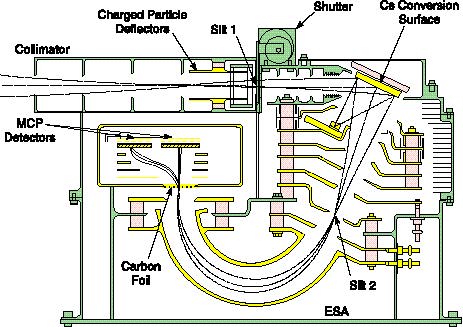
Fig. 2.b.1. LENA is a spherical electrostatic analyzer with TOF mass analysis and a Cs conversion surface that converts neutral atoms to negative ions.
Optics and Detectors. LENA [Ghielmetti et al., 1994] combines flight-proven plasma analyzer techniques with well-established, high- efficiency cesiated neutral-to-negative-ion surface conversion technology to measure composition and energy spectra of neutral atoms (H, D, 3He, 4He, and O) at 10-300 eV. LENA consists of a collimator, conversion unit, extraction lens and acceleration region, dispersive electrostatic energy analyzer, and TOF mass analyzer with position- sensitive particle detection (Fig. 2.b.1.). LENA's high geometric factor (0.2 cm2 sr) is achieved by simultaneously imaging in azimuthal angle, energy, and mass/charge (i. e., the spectrograph approach).
Particles enter the instrument through a collimator with elevation acceptance defined by the heights of the collimator and slit 1. A shutter located behind slit 1 will be closed to protect the conversion surface during launch and perigee portions of the orbit. Neutrals are converted to negative ions through near specular reflection from a low-work-function cesiated tungsten conversion surface [Wurz et al., 1995]. The surface is segmented to cover a 90 degrees azimuthal acceptance, with the facets aligned on a conical surface centered about the instrument axis of rotational symmetry (through slit 1). Laboratory tests of a prototype LENA have confirmed operation of the conversion surface, acceleration region, and electrostatic analyzer.
Laboratory testing of conversion surfaces at pressures significantly poorer than will be achieved on orbit has shown ionization efficiencies of 10-15% [Wurz et al., 1995]. Contamination of the surface will, in time, reduce conversion efficiency. Because there is a direct relationship between work function and conversion efficiency, in-situ monitoring of the work function gives conversion efficiency at any time. This monitoring is accomplished using laser diodes and the photoelectric effect at three different wavelengths. Based on laboratory data, we conservatively estimate that surface regeneration will be required at 10-day intervals. During regeneration, the instrument shutter is closed, high voltages turned off, and the surface heated to drive out impurities. The Cs dispenser, containing a non-volatile Cs salt, is switched on to deposit the single monolayer required. To avoid contamination within the rest of the instrument, the Cs generator dispenses a collimated beam to the surface. All nearby conductors are baffled.
Beyond the conversion surface, LENA is an ion mass spectrograph. Neutrals converted to negative ions at the Cs surface are accelerated away from the conversion surface and focused in the plane of slit 2. The negative ions are further accelerated to 20 keV between the object slit 2 and the spherical electrostatic analyzer. The electrostatic analyzer (operating at a fixed voltage) is dispersive in energy and focusing in elevation angle, so that it images the entire slit 2 onto the carbon foil of the TOF section.
The mass analyzer is similar to that of TIDE on Polar [Moore et al., 1995]. Secondary electrons produced on the back side of the foil are accelerated, deflected, and focused onto one MCP, producing the "start" pulse for the TOF and providing energy and polar angle information. The signal produced at the other MCP provides the "stop" pulse. The start and stop signals are obtained from 50%-transmission grids placed behind the respective MCPs. The position and TOF electronics are contained within a high-voltage bubble. The encoded information is transmitted across the high- voltage interface via fiber optics.
The three main sources of instrument background are UV photons, photoelectrons from the conversion surface, and negative ions produced by attachment of photoelectrons to residual gas molecules. UV photons scattered at near specular angles from the conversion surface enter a light trap at the back, while the electrostatic analyzer provides further multiple bounce rejection. Photoelectrons from the conversion surface are separated from the negative ions and diverted into a trap by a weak magnetic field between a small magnet at the back of the conversion surface and another at the dispenser. This magnetic field also traps electrons scattered through the collimator. Ion background from residual gas is minimized by accelerating photoelectrons away from the sensitive region. Any negative ions that are thereby produced will be discriminated against by their lower energies relative to those produced on the surface.
LENA has considerably lower mechanical tolerances and also lower detector position resolution than required by the Polar TIDE and TIMAS instruments, which are its heritage. A further simplification is that the LENA sensor and detector high-voltage power supplies operate at a fixed voltage, eliminating the need for high-voltage sweeping. The only portion of LENA without direct flight heritage is the conversion surface, with which we have extensive and ongoing laboratory experience [Wurz et al., 1995].
Sensor Electronics. LENA contains a single static 20-kV high-voltage supply from which all other ion deflection voltages are derived using taps on the high-voltage multiplier. The MCPs use a separate supply. Four energy levels and 11 angles are coded into a pixel array. Start/stop events are measured in a time-to-amplitude converter, digitized, and then recorded and tagged with pixel location. Events are binned in cadence with spacecraft spin to produce 8 x 8 degrees angular pixels.
Operation. LENA has one operation mode and one surface regeneration mode. In a typical orbit, the shutter will open after a perigee pass, and low-energy neutral atom imaging will proceed throughout the orbit until near perigee, when the shutter will close again. Approximately every 10 days the instrument will be cycled autonomously through the conversion surface regeneration mode described above.
Calibration. Instrument calibration prior to launch will be performed at GSFC and at the University of Denver neutral beam facilities using H and O neutral beams.
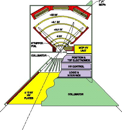
2.b.1.b. Medium Energy Neutral Atom [MENA] Imager. The MENA imager relies on thin carbon foils to convert neutral atoms into ions [cf. McComas et al., 1994]. However, while McComas et al. describe an energy spectrometer (which allows only one energy to be detected at a time), MENA is an energy-angle-mass spectrograph that samples and resolves simultaneously all energies, all polar angles within a 90 degree fan, and all masses. This spectrographic feature is very important for magnetospheric imaging because the weak fluxes of neutral atoms require an instrument with a high duty cycle.
Optics and Detectors. The MENA analyzer (Fig. 2.b.2.) consists of elevation and azimuthal collimators, stripper foil, TOF analyzer [Young et al., 1992; Moore et al., 1995], and a cylindrically symmetric (with axis of symmetry lying in the page) electrostatic mirror spectrograph with well-known properties [Sar-El, 1967]. Collimator plates (described previously) reduce charged particle background and internal scattering. The other significant background that must be eliminated is ultraviolet light from the Sun and geocorona. A combination of a stripper foil and -5 kV post acceleration is used (1) to create positive ions that are deflected away from the UV line-of-sight and (2) to reject secondary photoelectrons. When transmission through the two foils, anti-reflection blackening of grids, and MCP efficiency for UV are taken into account, the MENA UV rejection rate is 10-9.
Fig. 2.b.2.a. MENA is an energy-angle-mass spectrograph that samples and resolves simultaneously all energies, all masses, and all polar angles within 90 degrees. This elevation view shows the ray-traced trajectories of ions created from neutrals with incident energies of 1 and 30 keV.
Ray paths are shown in Fig. 2.b.2.a. for incident neutral atoms with incident energies of 1 and 30 keV and in Fig. 2.b.2.b. for 30-keV atoms. The ions produced by the stripper foil are accelerated by -5 kV in the adjacent acceleration region. The cylindrical electric field forms an image in energy and polar angle of the 8 x 8 degrees collimated beam. The carbon foils are nominally 0.5 g/cm2 thick and of the same type and thickness used in our other TOF instruments [Young et al., 1992; Moore et al., 1995]. Energy-per-unit-charge and simultaneous velocity analysis (through TOF measurements made with the start/stop MCP) yield mass per unit charge with a resolution sufficient to separate H and O.
Fig. 2.b.2.b. Front view of MENA analyzer with trajectories of 30 keV atoms at three different polar entrance angles shows 90 degrees FOV.
Secondary electrons emerge from the back of the start TOF carbon foil placed above the MCP and are electrostatically accelerated down onto the MCP, which functions as both a start and stop detector (Fig. 2.b.2.a.). This arrangement is feasible because the ion travel times (5 to 300 ns) are short compared to the mean time between events (104 ns). The MCP records a start pulse for TOF analysis and also gives position for energy and polar angle identification. The stop pulse is produced by the same MCP to provide timing information. Neutral atoms, which are not deflected by the electric field, pass through a second cylindrical grid and are detected with the MCP shown near the top of the figures. Negative ions, which also emerge from the stripper foil in some fraction depending on atomic species and energy, will also be detected by the upper MCP. Thus, even though the analyzer is designed primarily for positive ions, particles that emerge as neutrals or negatives can also be detected and analyzed to obtain nearly 100% of the total incident neutral flux (the exact fraction is obtained from calibration). This feature gives MENA a key advantage over other designs that analyze only positive or negative ions [e.g., McComas et al., 1994]. A laboratory prototype of the MENA analyzer has been built and successfully tested at SwRI.
Sensor Electronics. MENA contains a static +20 kV deflection supply from which positive analyzer voltages are derived. A -5 kV potential derived from the -10 kV collimator supply is used to accelerate positive ions leaving the stripper foil at the entrance to the cylindrical analyzer. The neutral-atom and positive-ion MCPs are powered from two separate supplies. MENA detectors consist of two rectangular sections cut from standard Hammamatsu "Z-stack" MCPs. Four energy levels and 11 polar angles are coded into a pixel array. Start/stop events are measured in a time-to-amplitude converter, digitized, and then recorded and tagged with pixel location. Events are binned in cadence with spacecraft spin to produce images with 8 x 8 degrees angular resolution.
Operation. All MENA high voltages are static except for infrequent adjustments of MCP gain. After initial switch-on in orbit, MENA is simply allowed to run in a single operational mode. A monthly calibration mode is run to check MCP gain saturation, and pulsers are used to generate positional patterns that test the detector signal chains and encoding logic.
Calibration. The SwRI Ion/Electron/Neutral-Atom calibration facility will generate neutral atom beams of hydrogen and oxygen in the range 1 to 30 keV that will be used to test and calibrate MENA. The facility's duoplasmatron source provides a collimated neutral flux equivalent to 10-14 Amp/cm2 (any larger current would saturate the MENA detection system). The facility includes a 4 degree-of-freedom goniometer capable of holding MENA-sized instruments.
2.b.1.c. High Energy Neutral Atom (HENA) Imager. At higher energies (>10 keV for H and >40 keV for O), individual neutral atoms can be directly detected with good energy resolution by low-noise solid state detectors (SSDs). Each neutral atom's mass (M) and energy (E) are identified unambiguously by the proven technique of measuring the speed by time-of-flight (TOF) and residual energy by pulse-height (PH)a method first published by Gloeckler and Hsieh [1979] and later employed in various configurations in AMPTE/CCE and GGS/WIND, and to be flown on Cassini/MIMI. Advanced imaging capability is achieved by using a 1-D strip- SSD, each strip having a field-of-view (FOV) defined by the ion-rejecting collimator to represent a polar ([[theta]]) sector of arrival for a given azimuthal ([[phi]]) sector defined by the spacecraft spin. Thus, the detected atoms are grouped into a matrix (M, E, [[theta]], [[phi]]), forming the basic data base. HENA has two identical sensor heads, each having two identical TOF/PH analyzers.
Optics and Detectors. HENA acquires angular images using a multi- channel fan-shaped collimator that also serves to suppress charged particle entry by biasing adjacent collimating plates at +/- 10 kV. Fig. 2.b.3. shows the collimator and TOF/PH analyzer in half of a sensor head. A 1-D strip-SSD (20 strips per analyzer) over-samples the 10 angular channels of the collimator, forming a 2D image in ([[theta]], [[phi]]) when binned by spin azimuth angle. Collimator channels and strip-SSDs define 8 degrees [[theta]]-sectors over the 90deg. [[theta]]-FOV for each 8deg. [[phi]]-sector. A 5 ug cm-2 Si/polymead/C foil was chosen to reduce scattering and is possible because of the immunity of the strip-SSDs to EUV. Secondary electrons generated on the back side of the foil (Fig. 2.b.3.) are guided to the Start half of the MCP by a carefully designed electric field. Symmetry of this field allows secondary electrons generated on the surface of the SSD to be guided by the same electric field to the Stop half of the MCP. The short TOF path (2.3 cm) allows sufficient resolution (2 ns between 4 and 65 ns) for separating H from O in the TOF/PH analysis and effectively reduces accidental coincidence rates. The MCPs are rectangular "Z stacks" of three 100 mm 15 mm plates to provide ample gain reserve. With its 1.6 cm2 sr geometrical factor and overall sensitivity of 0.58 for TOF only and 0.41 for TOF/PH, simulations indicate that HENA will gather ~3 events/pixel/minute when viewing the quiet ring current and~300 events/pixel/minute during storm main phase.
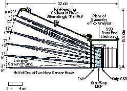
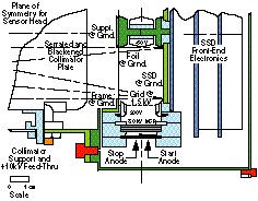
Fig. 2.b.3. Half of a HENA sensor head (top) and schematic of the TOF/PHA detector (bottom).
Sensor Electronics. The HENA TOF electronics are essentially identical to those used on Cassini/MIMI, which in turn are based on earlier experience with AMPTE/CCE and GGS/WIND. The SSD electronics utilize the flight-proven AMPTEK A250 hybrid charge-sensitive amplifiers (44 per sensor head) followed by shaping and logic based on the microelectronics of Polar/SEPS [Blake et al., 1995]. Pre-amplification is done within the sensor heads, while TOF and PH analysis are performed on boards within the rectangular box sandwiched between the heads.
Operation. All HENA potentials are static except for infrequent adjustments of MCP gain. After activation and checkout, HENA runs in a single operational mode. Some choices of data product priorities can be made as software options, providing, for example, a periodic (e.g., monthly) calibration mode to check the TOF/PH identification of atomic species, the pulse-amplifier chains, and the binning logic.
Calibration. HENA will be calibrated using ion accelerators at GSFC and Taylor University and a solar-constant UV source at MSFC. The ion accelerators provide a small collimated neutral atom flux in the presence of a much larger ion flux, which is a good simulation of conditions in which HENA will operate.
2.b.2. Photon Imagers. There are three photon imagers on IMAGE. The EUV instrument images resonantly scattered solar emissions from plasmaspheric He+ at 30.4 nm. Two FUV instruments, SI (Spectrographic Imager) and WIC (Wideband Imaging Camera) image the Earth's auroral emissions in several FUV wavelengths. General characteristics of the imagers are listed in Table 2.b.2.
2.b.2.a. He+ 30.4 nm Imager (EUV). Effective imaging of plasmaspheric He+ requires global "snapshots" in which the high apogee of the IMAGE mission and the wide FOV of the EUV imager provide, in a single exposure, a map of the entire plasmasphere from the outside with a sensitivity of 0.2 count/s-pixel-Rayleigh (R), a spatial resolution of 0.1 RE, and a time resolution of several minutes. The 30.4-nm feature is easy to measure because it is the brightest ion emission from the plasmasphere, it is spectrally isolated, and the background is negligible. Measurements are easy to interpret because the plasmaspheric He+ emission is optically thin, so its brightness is directly proportional to the He+ column abundance. Since the 1970's, EUV photometers in LEO have produced "inside-out"images of the plasmasphere with a brightness of ~10 R.
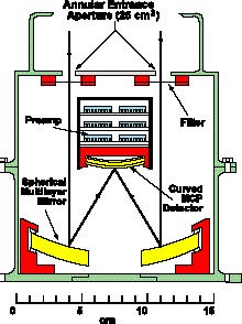
Fig. 2.b.4. Schematic of one of the three identical EUV (He+ 30.4 nm) imager sensor heads. Internal baffling is not shown. The design is that of EUVI, a He+ imager that will fly on the Shuttle in July 1997.
|
Inst |
Measurement Type |
Focal Length (mm) |
Aperture (mm2) |
L.(nm) |
L.Res. (nm) |
Instant FOV (deg) |
Tot. FOV (deg) |
Pixel FOV (deg) |
Sensitivity (c/R/px) |
Time Res. (min) |
Spat. Res. @7RE (km/pix) |
|---|---|---|---|---|---|---|---|---|---|---|---|
|
EUV |
Plasmaspheric He+ 30.4 nm |
75 |
25 (x3) |
30.4 |
5.0 |
30x90 |
90x360 |
0.5x 0.5 |
2.4 |
2 |
640x640 |
|
FUV/SI |
Auroral LBH (narrow band), Ly-[[alpha]] |
89 |
3.9 |
121.6, |
0.2, |
16x6.5 |
16x360 |
0.13x0.13 |
0.04 |
2 |
100x100 |
|
FUV/WICv |
Auroral LBH (broad band) |
22.4 |
60.8 |
134-160 |
26 |
30x22 |
30x360 |
0.07x0.07 |
0.1 |
2 |
60x60 |
EUV consists of three identical sensor heads (Fig. 2.b.4.) serviced by a common electronics module. It employs elements of new technology, multilayer mirrors. Because it is simple and lacks moving parts, the EUV is rugged and reliable. Each sensor head has a field of view of 30 x 30 degrees. The three sensors are tilted relative to one another to cover a fan-shaped instantaneous FOV of 90 x 30 degrees. As the satellite spins, the fan sweeps a 90 x 360 degrees swath across the sky.
Optics and Detector. Each EUV sensor achieves high throughput and a wide field of view by using a large entrance aperture and a single spherical mirror. A multilayer reflective coating on the mirror selects a narrow 5-nm passband around the 30.4 nm line. To circumvent the red leak in the multilayer mirror, the filter blocks H Lyman [[alpha]] contamination from the geocorona. The detector consists of two curved, tandem MCPs with an alkali halide front surface photocathode. The detector's spherical input surface minimizes the effects of spherical aberration. Readout from the detector is from a 128 128 wedge and strip anode. The sensitivity (accounting for the duty cycle inherent in a spinning spacecraft) is 0.2 count/(sec pixel) per Rayleigh, where the pixel size is taken to be 0.1 RE. By summing pixels to make a spatial resolution element (called a resel) of 0.5 RE, the count rate is 5 counts/(sec resel) per R.
Electronics. Each sensor has its own preamplifiers and high- voltage power supply. Signals from the preamps are processed by position- finding circuitry in the central electronics module, which also includes the control microprocessor (CMP), a RAM buffer, and A/D converters for housekeeping information. The CMP accepts commands from the CIDP to select operating modes, spatial resolution, etc. The satellite provides a spin-phase sync signal to the EUV.
Operation. A key element in the operation of the EUV is the RAM buffer, which stores a 2-D array of brightness measurements. Each element in the array corresponds to a particular spatial resolution element in the sky. EUV keeps track of the satellite's spin phase, so the CMP can relate the position of each detected photon to an absolute position in the sky. It then increments the value of the corresponding array element. After a number of spins corresponding to the desired time resolution, the CIDP commands a read-out of the map buffer, compresses the image, and formats it for the telemetry stream. EUV's data rate is 1.5 kbps for about 90% of an orbit and increases to 4.5 kbps near perigee.
When the satellite is near apogee, the plasmasphere will fill about 30% of the sky. The range of the map buffer and the angular size of a resel will be set appropriately by autonomous command. When the satellite is near perigee, plasmaspheric emission will fill much of the sky. Then the range of the map will be increased, and the angular resolution will be reduced.
For some orientations of the spin axis, the Sun may enter the FOV of one of the sensor heads at some spin phases. No useful data can be recorded from the affected sensor head with the Sun in the field, and the EUV control microprocessor will automatically reduce the high voltage to the MCPs to avoid excessive counting rates. The filter will prevent damage to the detector by focused visible sunlight.
Heritage. The sensor heads are similar to the soft x-ray telescopes developed for the Earth-orbiting satellite Alexis. The multilayer coating techniques are now quite mature. The detector is similar to others used routinely, including those developed by the University of Arizona IMAGE team members. We are presently fabricating the EUVI, a He+ imager of the design proposed here, that will fly on the Shuttle in July 1997. Test results will be available prior to the IMAGE instrument fabrication phase.
Calibration. The EUV will be calibrated at the University of Arizona Lunar and Planetary Laboratory (LPL) EUV Calibration Facility. We will calibrate the sensor heads separately, by mounting each head in a gimbal that permits rotation about two orthogonal axes and translation along two orthogonal axes. With the entrance aperture illuminated by a collimated beam of 30.4-nm radiation of known intensity, we will record the response of the EUV as the head is rotated to probe the full field of view.
2.b.2.b. Far Ultraviolet Imagers (FUV). Science requirements driving FUV imager designs are (1) to image the entire auroral oval from a spinning spacecraft at 7 RE apogee altitude, (2) to separate spectrally the hot proton precipitation from the statistical noise of the intense, cold geocorona, and (3) to separate spectrally the electron and proton auroras. FUV consists of two imagers that combine high spectral discrimination, high spatial resolution, and the greatest possible sensitivity to meet these requirements.
In the FUV range up to ~160 nm, there are several bright auroral emission features that compete with the dayglow emissions. For the electron aurora, the brightest is 130.4 nm OI, which is multiply scattered in the atmosphere and thus cannot be used for auroral morphology studies. The next brightest is the 135.6 nm OI emission [Strickland and Anderson, 1983]. Separation of the 130.4 and 135.6 nm lines necessitates the use of a spectrometer because even reflective narrow-band filter technology cannot satisfy the ~3 nm wavelength resolution requirement. Above 135.6 nm, weak LBH lines can be detected using narrow-band filter technology. Separate imaging of the intense, cold geocorona (Lyman [[alpha]] emissions at 121.6 nm) and the less intense, Doppler-shifted Lyman [[alpha]] auroral emissions requires significantly higher spectral resolution (0.2 nm).
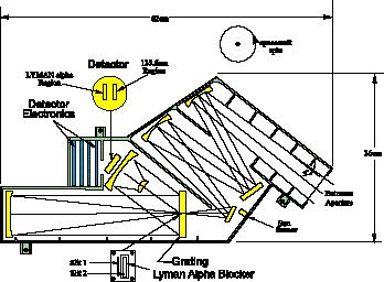
Fig. 2.b.4.a. The IMAGE Spectrographic Imager (SI) is actually two imagers in one: high spectral resolution of Lyman emissions is achieved with slit 1; lower spectral resolution of LBH bands is achieved with slit 2.
Spectrographic Imager (SI). The relatively high wavelength resolution requirement is satisfied by the SI. The 0.2-nm wavelength resolution drives the size of the instrument and consequently the number of mirrors in the optics system. Also the narrowness of the slits in the spectrometer limit the dwell time during which a pixel is in the field of view.
Optics and Detector. The SI (Fig. 2.b.4.) is actually two spectrometers. It has two closely spaced parallel slits located in a cut-out in the center of the grating. The two slits are positioned parallel to the satellite spin axis and scan the Earth once per rotation. The narrow slit (slit 1) provides a wavelength resolution of 0.2 nm. The narrow width of this slit, combined with the 0.1 nm spectral resolution of the system, allows the imager to distinguish between, and separately measure, the central core of the Lyman [[alpha]] emissions (geocorona) and the Doppler-shifted components (proton aurora). The wider slit (slit 2) produces a wavelength resolution of 3 nm. This slit is used to measure the OI 135.6 nm emission with adequate spectral resolution to distinguish it from the brighter OI 130.4 nm emission and has a blocking transmission filter to suppress the bright Lyman emission. There are two regions of interest on the detector. The first region contains the Lyman [[alpha]] (121.6 nm) emissions from the geocorona and proton aurora through slit 1. The second region contains the 135.6 nm emissions from the electron aurora through slit 2. This region actually consists of a variety of electron aurora emissions: about 80% OI 135.6 nm, about 20% 135.4 nm LBH, and also a negligible amount (~2%) of additional LBH at 140 nm that enters through the narrow slit 1.
The detector uses a KBr photocathode on a MgF2 window image tube with MCP intensification. The intensified image is detected by a crossed delay-line type detector with two 32 x 128 pixel active areas. The narrowness of slit 1 assures that the detector is not saturated even with full nadir Lyman [[alpha]] dayglow/geocoronal emission in the field of view.
Electronics. The detector preamps and high-voltage power supplies are housed in the sensor box near the detector (Fig. 2.b.4.a.). Like the other photon sensors, the SI detects the position of every photoelectron by position-finding circuitry, and the images are produced in RAM memory by integrating the detected pulses according to a look-up table that is dependent on the rotation phase of the spacecraft.
Operation. The SI operation is very similar to that of EUV, except that the RAM memory stores a 2-D array of brightness measurements for two separate wavelengths (121.6 and 135.6 nm) instead of one. The SI has only one mode of operation. For some orientations of the spin axis, the Sun may enter the field of view of SI at some spin phases. As with EUV, the control microprocessor will automatically reduce the high voltage to the MCPs to avoid excessive counting rates. The filters will prevent damage to the detector by focused visible sunlight.
Heritage. The SI design is derived from the University of Arizona Glow Spectrometer and the Dual Range FUV spectrograph in the Solar Plasma Diagnostic Experiment. A full ray tracing design has been performed for the system. The detector design was developed jointly by UC Berkeley and Lockheed Palo Alto Research Lab for the SOHO spacecraft.
Calibration. The calibration of all the UV instruments is relatively conventional. All imagers will be calibrated for absolute sensitivity as a function of wavelength in band and out of band. It is important to determine the response of the instrument to natural sunlight as reflected from objects such as white clouds. Also, every pixel will be measured in the calibration to determine any geometric distortion as required for the flight software. Facilities exist at all photon imager institutions to perform these calibrations. For SI, the University of Liège will perform mechanical alignment, Lockheed will perform detector and initial calibration, and GSFC will perform final preflight calibration.
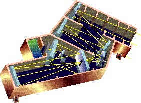
Fig. 2.b.4.b. The SI, shown here in a cutaway view, employs novel, low-risk, fixed-optics technology to achieve dual-wavelength imaging.
Wideband imaging camera (WIC). The relatively high sensitivity requirement for auroral imaging is satisfied by the WIC. This imaging camera uses the basic design flown on the Viking and Freja satellites (Figure 2.b.5.) to measure the auroral LBH emissions in a relatively broad band from 134 nm to 160 nm [Anger et al., 1987]. The large field of view permits a long dwell (or integration) period and increases the apparent sensitivity.
Optics and Detector. The WIC optics design is identical to that of the Freja camera. Incident photons pass through a filter that blocks the Lyman [[alpha]] emissions and protects the detector from direct, focused sunlight (Fig. 2.b.5.). The primary and secondary mirrors have a coating that is highly reflective (>60%) in the FUV but has minimum (<3%) reflectance out of band. The detector uses a CsI photocathode on a BaF2 window. MCPs are used to intensify the image, which is produced on a phosphor and fiber-optically coupled to a diode array.
Electronics and Operation. Electronics and operation of the WIC are essentially identical to those of SI. Readout occurs once per 0.1deg. of rotation for a frame rate of 30 frames/s at 0.5 rpm. The camera data are digitized and co-added in memory; the addresses are selected according to the rotational phase of the spacecraft. This technique minimizes the distortion correction required by the imager.
Heritage. The WIC is a direct copy of the Viking and Freja wideband cameras with the CCD detector replaced by a diode array detector to minimize radiation susceptibility. Such diode array detectors have been flown by Lockheed in the DoD ERIS program.
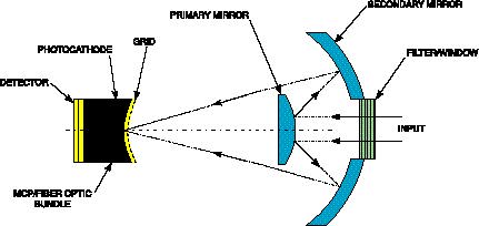
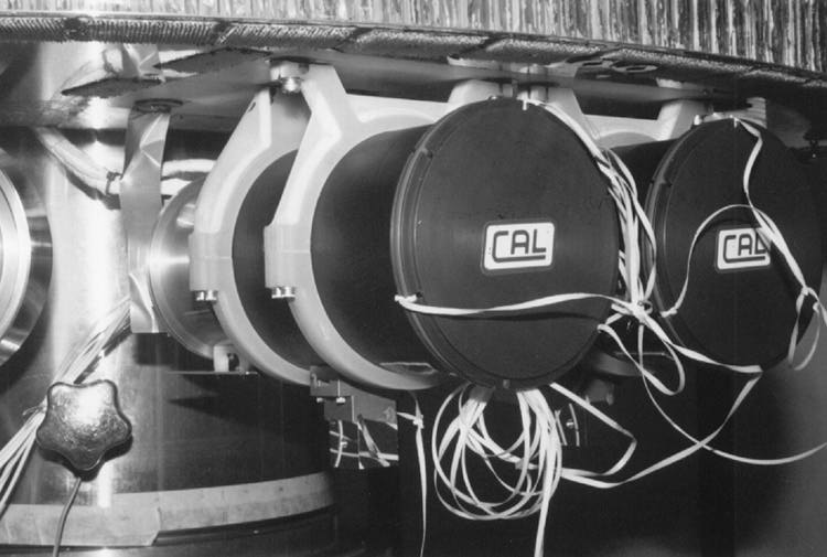
Fig. 2.b.5. A copy of the WICs flown successfully on Viking and Freja, the IMAGE WIC will provide high-sensitivity images of auroral LBH emissions. A photo of the wideband cameras on Freja.
Calibration. The WIC will be calibrated by the University of Calgary using methods similar to those described above for SI.
2.b.3. Radio Plasma Imager. The Radio Plasma Imager (RPI) is a transmitter/receiver system that responds to the science requirement for the continuous remote sensing of plasma densities, structures and dynamics in the magnetosphere and plasmasphere. The instrument measures the time delay, angle-of-arrival, and Doppler shift of magnetospheric echoes over the frequency band from 3 kHz to 3 MHz. This frequency range makes possible remote sensing of plasma densities from 0.1 to 105 cm-3. Programmable operational modes selected within the limits listed in Tables 2.b.3. and 2.b.4. will focus on specific magnetospheric and plasmaspheric features.
|
Measurement |
Nominal Res. |
Limits |
|---|---|---|
|
Echo Range |
500 km |
0.1 to 20 RE |
|
Angle-of-Arrival |
1 deg. |
Function of S/N |
|
e Density |
10% |
0.1% |
|
Doppler |
0.125 Hz |
0.004 to 0.3 Hz |
|
Time |
8 sec. |
4 sec to 34 min |
|
Parameter |
Nominal |
Limits |
|---|---|---|
|
RF Power |
10 W |
10 W+ |
|
Pulse Width |
53 msec |
3.3 to 210 msec |
|
Receiver Bandwidth |
300 Hz |
fixed |
|
Pulse Rate |
2 pps |
1 to 5 pps |
|
Frequency Range |
10-1000kHzv |
3 kHz to 3 MHz |
|
Frequency Steps |
5% |
> 1Hz |
|
Coherent Integ. Time |
8 sec. |
4 sec to 34 min. |
|
+Antenna voltage is maintained 3 kV; power drops below 10 W at frequencies below 100 kHz. | ||
RPI Configuration. RPI will have two crossed 400-m tip-to-tip thin wire dipole antennas in the spin plane, and a 10-m tip-to-tip tubular dipole antenna along the spin axis (Fig. 2.b.6.). All three antennas will be used for reception to determine the angles of arrival of the echoes [Calvert et al., 1995].
RPI Electronics. The RPI electronics will be housed together with the CIDP in an electrically shielded box. RPI is a space-qualified adaptation of the state-of-the-art Digisonde Portable Sounder (DPS) [Reinisch et al., 1992, 1995; Reinisch, 1995]. Eighteen DPS units are operating worldwide, and 15 more are currently being deployed. The transmitters use solid-state MOSFET push-pull final amplifiers with ferrite core transformers. The two spin-plane antennas are driven +/-90 degrees out-of-phase, resulting in right/left-hand circularly or elliptically polarized signals. The signal waveform (pulse width and repetition rate, intra- and inter-pulse phase coding and wave polarization) is software controlled on a pulse-by-pulse basis, providing the needed mode selection flexibility. The digitally synthesized super-heterodyne receivers are derived from the DPS design.
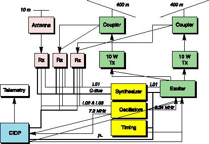
Fig. 2.b.6. RPI is a straightforward spaceborne adaptation of the Digisonde Portable Sounder system.
Signal Processing, Signal-to-Noise Ratio, and Spatial and Time Resolution. The large distances, low power, and short antennas (relative to the wavelength) require onboard signal processing. Pulse compression and coherent spectral integration techniques developed for the DPS will be used to achieve the required signal-to-noise (S/N) ratios. The calculated worst case S/N before (right axis) and after (left axis) digital processing for echoes from the magnetopause, plasmapause, and plasmasphere are shown in Fig. 2.b.7. for a typical digital processing gain of 21 dB. For a large part of the frequency range, S/N is larger than 100, assuring 1 degree angular resolution. The range resolution of 500 km is defined by the 3.3-ms width of the transmitted pulses. The number of sounding frequencies selected for a given measurement, together with the coherent integration time, determines the time resolution, since measurements are taken continuously.
Fig. 2.b.7. Digital signal integration will allow remote sensing of most of the magnetosphere [after Calvert et al., 1995].
2.b.4. Central Instrument Data Processor (CIDP). The CIDP consists of a RAD-6000SC central processor, 250 MB solid-state memory with telemetry interface, instrument communications board, RPI signal processing electronics, and a DC/DC converter subsystem. All circuit boards are packaged in 6U VME form factor. The CIDP is based on an existing flight computer developed by SwRI for the CSAT commercial communications satellite (Fig. 2.b.8.) and under development for the International Space Station Alpha (ISSA) Furnace Facility.
Employing the Loral Federal Systems RAD-6000SC 32-bit, radiation hardened, reduced instruction set (RISC) CPU, the CIDP is capable of over 25 MIPS performance at maximum clock frequency. Power consumption can be reduced by lowering the CPU's clock frequencies by changing control registers in software. With a total dose resistance of >106 rads (Si), a single event upset LET of >80, and totally latchup-free operation, the RAD-6000SC is the optimum control processor for IMAGE. The RAD-6000SC was developed for the Mars Environmental Survey Mission and is fully flight qualified. With the exception of the instrument communications board, all CIDP subsystems are fully developed. The CIDP will be produced by the SwRI spacecraft computer development group, an organization with over 30 successful missions to its credit.
The CIDP provides the following support services to the IMAGE science instruments: (1) instrument data acquisition, compression, and storage; (2) onboard data processing; (3) uplink command processing, routing, and scheduling; (4) formatting of stored data for telemetry downlink; (5) health and status monitoring; and (6) communications interface to spacecraft Mission Unique Electronics (MUE). In operation the CIDP will acquire instrument data over RS-485 serial communications lines; compress, bin, or sort the data as required for each instrument; and store the data in compressed format in the solid-state memory. Orbit state-vector information and time will be acquired from the spacecraft MUE and included with the instrument data packets. Ground commands will be passed to the CIDP from the spacecraft transponder. After error checking, the command loads will be passed to the science instruments' embedded microcontrollers. Commands can also be stored for later execution. When enabled to do so by the spacecraft MUE, the CIDP will transfer the contents of its solid state memory for downlink at 2.2 Mb/s.

Fig. 2.b.8. CIDP design will be based on the C&DH system for the CSAT commercial communications satellite, shown here, and the ISSA Furnace Facility processor now under development.
Software resident in the CIDP will consist of the VxWorks operating system (produced by Wind River Systems, Inc.), I/O device drivers, and the applications software used in instrument operations. This same operating system is currently in use in two other RAD-6000-based flight computers being built by SwRI. Applications software for both the microcontrollers and the RAD-6000 will be written in ANSI Standard C. IMAGE software will be developed in a controlled, structured, and well-documented manner with emphasis on configuration control using the ISO 9001-3 software assurance system.
2.b.5. Instrument Requirements Summary. A summary of the resource requirements of the complete set of IMAGE instruments is shown in Table 2.b.5.
2.c. IMAGE Spacecraft
The IMAGE mission will use a NASA-provided spacecraft based on the Small Explorer (SMEX) Fast Auroral Snapshot Explorer (FAST). FAST is an existing spacecraft of known cost. A full spacecraft design study completed at GSFC shows that the FAST system, with a larger solar array and battery, can be adapted to meet all IMAGE requirements within the MIDEX cost and resource limits.
FAST was chosen as the baseline for IMAGE because both missions require a spin-stabilized spacecraft with deployable wire booms and a body-mounted solar array, and both must withstand a high radiation environment. The IMAGE spacecraft diameter is 60% larger than FAST but will copy the simple FAST architecture (Fig. 2.c.1.), all components being either exact copies of, or based on, existing hardware. IMAGE will benefit from FAST and SMEX systems already developed.
Specifically, IMAGE will make use of:
This design approach provides ample mass and power margins, while minimizing risk and cost (Table 2.c.1.).
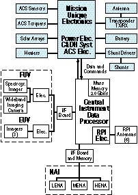
Fig. 2.c.1. IMAGE uses the FAST spacecraft architecture. (FAST subsystems are shaded.)
2.c.1. Instrument Accommodation. All instruments mount around the perimeter of a single deck (Fig. 2.c.2.). The NAI, EUV, and FUV instruments have fan-shaped fields of view parallel to the spin axis and centered on the spacecraft spin plane. The four RPI wire antenna deployers are mounted 90 degrees apart, oriented so the deployed antennas are perpendicular to the spin axis. The two RPI rigid axial antenna deployers are mounted at the center of the deck, one each on the top and bottom, and deploy along the spin axis.
Fig. 2.c.2. IMAGE instrument complement is easily accommodated by an enlarged FAST-based spacecraft.
Openings in the spacecraft bellyband allow instrument viewing and antenna deployment. Instrument fields of view are unobscured by the RPI antennas, and fine alignment is not required. Sunshades, baffling, and protective covers are integral to each sensor.
|
Instrument |
Mass (kg) |
Power (W) |
Data Rate (kbps) |
Dimensions* (LxWxH) (cm) |
FOV (deg) |
Heritage Instr/Spacecraft |
|---|---|---|---|---|---|---|
|
NAI |
| |||||
|
LENA |
8.0 |
5.3 |
1.0 |
33x29x31 |
8x90 |
TIDE,TIMAS/Polar |
|
MENA |
7.0 |
7.0 |
1.0 |
38x20x17 |
8x90 |
TIDE/Polar,CAPS/Cassini |
|
HENA |
8.0 |
12.0 |
2.5 |
35x38x34 |
8x90 |
MIMI/Cassini,SEPS/Polar |
|
FUV |
| |||||
|
SI |
8.7 |
6.0 |
6.0 |
62x36x16 |
16x1.2 |
SEPAC/AEPI |
|
WIC |
1.9 |
3.0 |
4.0 |
26x15x13 |
22.4x30 |
Viking, Freja |
|
Electronics |
2.6 |
3.0 |
n/a |
15x20x16 |
n/a |
SOHO, TRACE |
|
EUV |
| |||||
|
Sensor (3) |
6.8 (ttl) |
6.0 |
4.5 (ttl) |
15 (dia)x17 ea. |
30x90 |
Alexis, Viking |
|
Electronics |
3.5 |
n/a |
15x15x10 |
n/a |
Alexis | |
|
RPI |
| |||||
|
Antennas |
3.6 ea. |
0 |
0 |
36x18x18 |
n/a |
ISEE, WIND,WISP Rocket,Stacked Oscars on Scout (SOOS) |
|
Electronics, incl. CIDP |
11.0 |
11.8 |
7.0 |
36x27x14 |
n/a |
DPS, GP-B,Space Station Furnace |
|
Totals |
73.0 |
54.1 |
26.0 |
|
|
|
|
*Excludes collimator dimensions for LENA and MENA. | ||||||
Table 2.b.5. IMAGE science payload resource requirements summary.
2.c.2. Structure. The IMAGE structure (Fig. 2.c.3.) uses the FAST concept. The aluminum structure mates to the vehicle with the spin axis in the thrust direction. The design will be dynamically balanced and provides a spin to lateral moment of inertia ratio of 1.37 prior to boom deployment, which is greater than the 1.05 needed for spin stability.
|
Component |
Mass (kg) |
Orbit Avg. Power (W) |
Item Source or Heritage/Additional Information |
|---|---|---|---|
|
Instruments |
73.0 |
54.1 |
See Table 2.b.5. |
|
Spacecraft Subsystems |
|
|
|
|
Mission Unique Electronics (MUE) |
18.0 |
18.5 |
FAST MUE, with additional 3 kg shielding |
|
Wire Harness & Umbilicals |
15.0 |
|
|
|
Communications |
|
|
|
|
S-band transponder |
5.1 |
5.0 |
ACE, TRACE, & WIRE (add 1 kg. shielding) |
|
Antenna & cabling |
2.5 |
|
Medium Gain Belt Array |
|
Power |
|
|
|
|
Solar Arrays |
56.0 |
|
6.6m2 GaAs on aluminum honeycomb substrate |
|
Shunt control electronics |
1.4 |
5.0 |
FAST Shunt Control Electronicsv |
|
Battery (21A-hr) |
23.1 |
|
MIDEX/SMEX 21 A-hr super Ni-Cad |
|
Attitude Control |
|
|
|
|
ACS Torque rods |
15.4 |
5.3 (total) |
Ithaco Torqrods #D4311 (2) & #D42553 (1) |
|
Magnetometer |
1.0 |
SMEX 3-axis Magnetometer | |
|
ACS sensors |
1.0 |
Ithaco HCI(2) & Adcole FSS(1) as on FAST | |
|
Nutation damper |
5.0 |
FAST-type fluid damper | |
|
Mechanical |
|
|
|
|
Primary structure |
33.9 |
|
FAST-type aluminum structure |
|
Bellyband Structure &Radiator |
9.0 |
|
Aluminum with silver Teflon coating |
|
Battery Mount & Radiator |
3.0 |
|
Sized for 21 A-hr battery, incl. 1 face of bellyband |
|
Antenna Boom |
2.0 |
|
FAST-type composite antenna boom |
|
Fasteners, Misc. bracketry |
10.0 |
|
Based on FAST and SMEX S/C percentages |
|
Balance weights |
10.0 |
|
Based on preliminary C.G. offset and POI's |
|
Thermal Control |
|
|
|
|
Thermal blankets |
4.0 |
|
Aluminized Kapton multi-layer insulation |
|
Heaters and thermostats |
2.0 |
10.0 |
Minco film heaters and Elmwood thermostats |
|
Transponder heatsink |
1.1 |
|
per MIDEX AO Appendix B |
|
Spacecraft Bus Total |
218.5 |
43.8 |
|
|
IMAGE Total |
291.5 |
97.9 |
|
|
Capability |
373.0 |
129.8 |
Worst case, end of life |
|
Mass & power margins |
81.5 |
31.9 |
ACS torquers are not used after the first 40 days (spinup), resulting in 5.3 W additional margin. |
2.c.3. Command and Data Handling (C&DH) and Communications System. The C&DH and electrical system (Fig. 2.c.1.) is based on the FAST architecture and uses the FAST MUE. The MUE houses the spacecraft computer, power system, and ACS electronics. Use of the MUE allows extensive re-use of FAST software. Only two relatively minor changes to the MUE are required for this mission: (1) a modification to drive three torquers versus the two on FAST and (2) a modification to use two horizon-crossing indicators versus one on FAST.
The C&DH system provides ample data storage and downlink capacities (Table 2.c.2.). IMAGE will execute both real time and stored commands. Execution of stored commands will be within 100 msec of onboard Mission Elapsed Time (MET).The command load will be less than 30 kBytes with one command load per week sufficient for normal operations. The IMAGE instruments will use the timing capabilities provided by the MUE. The MUE provides MET and a 1-Hz clock. The required MET resolution of 10 ms and absolute accuracy of 5 s is within the MUE capability of 15-s resolution and 3 s accuracy.
The IMAGE communications system uses the SMEX 5-W S-band transponder. A medium-gain belt array antenna on a FAST type boom transmits and receives. Analysis shows a downlink margin of 8.8 dB with a bit error rate of 10-5 using a downlink rate of 2.2 Mbit/sec.
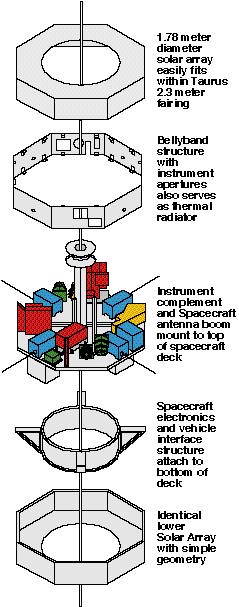
Fig. 2.c.3.IMAGE spacecraft exploded view shows its simple FAST-based design.
2.c.4. Power System. The power system consists of the SMEX 21 A-Hr Ni-Cad battery, a 6.6 m2 body-mounted solar array, the MUE power system electronics, and the FAST shunt control electronics. The solar array is GaAs with 1.5-mm coverglass to minimize charged particle damage. Resistors on the back of the solar array allow shunting of excess power. Unlike those on FAST, the upper and lower solar arrays are identical with simple geometry, flat sides, and minimal cutouts to reduce costs.
|
Combined instrument data rate |
26kb/sec |
|---|---|
|
Housekeeping data rate |
2 kb/sec |
|
Total data rate |
28 kb/sec |
|
Daily storage required (20% |
1.78 Gbits |
|
CIDP bulk memory |
2 Gbits |
|
Daily Downlink time @ 2.2 Mb/s |
13.45 min |
|
Available contact time per day |
~14.5 hr. |
Power system analysis shows the output from the solar arrays varies as a function of the spin axis to the sun-line angle (Fig. 2.c.4.). This angle never falls below 23.5 because of the 90 degrees inclination orbit with a RAAN of 0 or 180 degrees. The battery provides ample capacity for initial attitude acquisition and allows the spacecraft and instruments to operate nominally through eclipse periods of up to 89 minutes. GSFC orbit analysis shows the longest eclipse period to be 78 minutes.
Fig. 2.c.4. IMAGE Power System provides ample end-of-life power during all spacecraft attitudes and eclipses.
2.c.5. Attitude Control System (ACS). The IMAGE ACS is identical to that on FAST, except that three torque rods are used instead of two magnetic coils on FAST, and two Horizon Crossing Indicators (HCIs) are used instead of one on FAST. The MUE houses the ACS electronics. The ACS sensors consist of the two HCIs, a Fan Sun Sensor (FSS), and three-axis magnetometer. The HCIs provide spin angle and rate by detecting the Earth's horizon every spacecraft revolution and provide spin-axis attitude from the difference between the two HCI readings. The FSS provides the Sun's attitude, from which coarse spin-axis attitude is determined. The magnetometer measures the Earth's magnetic field as required to perform magnetic torquing. A fluid damper is included to reduce spacecraft nutation.
ACS simulations performed by GSFC for FAST with 2 HCIs have demonstrated spin-angle and spin-axis knowledge accuracies that meet IMAGE requirements (Table 2.c.3.). The Ithaco HCIs have been used at altitudes of up to 20 RE, greater than the 7 RE maximum altitude of IMAGE.
|
Attitude Knowledge |
FAST Performance(2 HCI's) |
IMAGE Requirement |
|---|---|---|
|
Spin Angle |
0.042 degree |
0.1 degree |
2.c.6. Thermal Control System. The IMAGE thermal design is similar to FAST in that all components mount to the aluminum deck, which also serves as a heat sink. The deck conducts heat to the bellyband radiator (Fig. 2.c.3.). The spacecraft interior is covered with multi-layer thermal blankets, and the solar arrays are thermally isolated from the spacecraft. Analysis shows that with an orbit average power of 94.2 W and a silver Teflon radiator of about 0.5 m2, the spacecraft is kept within its operating limits with minimal heater power (Table 2.c.4.). The spacecraft battery is thermally isolated with a separate radiator to maintain its tighter temperature limits. If required, thermostatically controlled heaters will maintain operating and survival temperatures.
|
Component |
Operational Limits |
Survival Limits |
|---|---|---|
|
S/C Electronics |
-10 to 40 |
-30 to 50 [deg. C] |
|
Instruments |
-10 to 30 |
-30 to 50 [deg. C] |
|
Battery |
0 to 20 |
-10 to 30 [deg. C] |
2.c.7. Contamination Control. Several IMAGE instruments are susceptible to molecular contamination, particularly from hydrocarbons and water vapor. By using clean rooms with instrument purging and standard materials selection practices, instrument integrity will be protected.
2.c.8. Radiation Protection. IMAGE will copy the FAST approach to radiation protection of using 30-krad rated parts and providing shielding to reduce total dose to the 30-krad level. A total radiation dose analysis was performed for the IMAGE orbit by SwRI. By providing minimum shielding at the box level equivalent to 3.8 mm of aluminum, the predicted radiation dose on the spacecraft and instrument parts is limited to 30 krad. Additional shielding is required on the MUE and transponder, which has been accounted for in the spacecraft mass budget.
2.c.9. Electromagnetic Interference and Electromagnetic Compatibility (EMI/EMC). The IMAGE spacecraft does not contain any highly EMI- susceptible instruments such as low-energy plasma instruments. Thus, standard spacecraft engineering practices are expected to provide adequate protection even in the presence of the RPI instrument, which transmits peak radio pulses of 10 W at frequencies from 100 kHz to 3 MHz, falling linearly with frequency to 0.1 W at 3 kHz. To assure that this output does not interfere with spacecraft or instrument systems, all instruments and spacecraft systems will be tested in radiation fields well in excess of the RPI levels throughout the entire frequency range of RPI operation.
2.c.10. Government Facilities. The IMAGE spacecraft development team plans to use NASA GSFC integration and environmental test and UV calibration facilities. No new or mission unique facilities are required.
2.d. Manufacturing, Integration, and Test.
The IMAGE manufacturing strategy involves assigning responsibility for support systems used in multiple instruments (e.g., HVPS, detectors, etc.) to one team member. The team members assigned such responsibility have demonstrated their abilities to build high-reliability systems on multiple missions. Examples include the production of high-voltage power supplies by the University of Maryland and the production of MCP detector systems by ISAS. Table 2.d.1. shows the institutions responsible for development, test, and calibration of each instrument.
2.d.1. Schedule. The schedule for the IMAGE science planning and instrument development, test and integration is shown in Fig. 2.d.1. Details are contained in Volume II.
|
SwRI |
Integration of science payload |
|---|---|
|
GSFC |
Development of LENA mechanical systems |
|
MSFC |
Fabrication and test of FUV WIC |
|
LPARL |
Development of FUV SI |
|
U.Md |
Development of FUV SI |
|
U.Ariz. |
Development of EUV |
|
U.Mass. |
Design of RPI |
|
AEC-Able Engineering will provide RPI antennas and
deployers. | |
2.d.2. Manufacturing Processes. Manufacturing processes for IMAGE instruments are well-established, mature processes performed by experienced operators. The list of common processes includes the following: (1) machining; (2) anodizing; (3) alodining; (4) soldering (surface mount and through hole); (5) conformal coating; (6) crimping; (7) electrostatic discharge machining; and (8) aluminum and gold blackening. All processes are performed with written procedures and are monitored by team-member QA inspectors. Post-processing inspection by QA inspectors is a normal part of the process close-out.
2.d.3. Software Production. As described in Volume II, our software development process is based on MIL-STD-498 and the guidelines of the Software Engineering Institute's (SEI) Capability Maturity Model (CMM). Requirements for software will be documented in a software requirements document. Design for software will be documented in a software design specification. We will produce our software in ANSI Standard C developed under the Greenhills Corp. software development environment hosted on a SunSparc or IBM R-6000 work station. A "chip -on- processor" (COP) emulator port on the RAD-6000SC allows comprehensive test and debug support. The C++ applications code will run under VxWorks Ver. 5.1. Device drivers for most I/O devices are available as COTS item from Wind River Systems or IBM. Custom device drivers can be written if necessary. All software procedures will be tested using written test procedures. Software will be maintained under configuration control using SEI-CMM Level 2, beginning at the software CDR.
Fig. 2.d.1. IMAGE instrument definition, development, test and integration schedule.
2.d.4. The Transition from Design to Production. Instrument designs are transitioned to production only after a thorough design review process has been completed. For each instrument, two IMAGE team design reviews are scheduled. In addition, the IMAGE Independent Review Team (see Vol. II) will be asked for a recommendation on the suitability of a design for production. The P.I. will make the final decision on suitability for production based on the recommendation from the responsible instrument team leader and his management team.
2.e. Mission Operations and Ground Data Systems
The IMAGE data system has been designed with an end-to-end approach, eliminating the problems associated with separating spacecraft design, ground system, and mission operations. The design eliminates duplication of effort and addresses the needs not only of the IMAGE team but of the scientific community and the public as well. The IMAGE mission operations and data flow systems are characterized by seamless integration with the Internet and World Wide Web (WWW). Nearly all transactions among science investigators, participating scientists, engineers, and the public will be handled via Web-browser interfaces. All relevant mission documentation will be published on-line, as well as by conventional means when needed, to ensure the widest and most timely availability possible.
A functional diagram of the ground data system is shown in Fig. 2.e.1. The telemetry stream will be routed into the IMAGE Science and Missions Operation Center (SMOC) at GSFC. The SMOC is based on similar facilities for the SMEX program and will consist of a number of workstations and support systems. The SMOC handles the health and safety functions of the spacecraft. IMAGE team members will check on the health and safety of their instruments through their SMOC Internet interface. The SMOC will also take the input data stream and decommutate and format the data into arrays for each instrument. Each array corresponds to a raw image browse product, which is generated by the SMOC from software provided by the instrument team. The level-0 data and browse products are immediately sent to NSSDC and to the instrument teams. The IMAGE team will provide to the NSSDC various higher-level data products (fully calibrated images in geophysical coordinates), along with all associated software tools. The scientific community and general public will access IMAGE data directly from NSSDC through the WWW. The browse products will be the main source of data for the general public and educational outreach programs as described in Vol. II. Staffing has been identified to maintain these public areas and provide technical support.
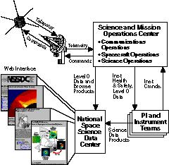
Fig. 2.e.1. IMAGE uses existing Explorer ground data systems.
Instrumenters will develop command sequences at their own institutions and send them to SwRI for integration into command loads. The SMOC will receive the loads and will verify them before uploading to the spacecraft over a secure network.
2.f. Performance Assurance (PA)
The PA program for IMAGE consists of the following elements: (1) safety assurance; (2) reliability engineering; (3) quality assurance; (4) parts, materials and processes; and (5) project reviews. In the development of our PA program we have taken guidance from GSFC-410-MIDEX-001 and GSFC- 410-MIDEX-002. SwRI will manage the PA program for the IMAGE instrument team. SwRI safety, reliability, and quality assurance engineers (QAEs) will work with team members to develop implementation plans for each of the five major elements of the PA program. Contained within our Instrument Development Plans (IDPs) will be agreements from each team member to comply with the IMAGE PA program. The SwRI PA lead engineer will serve as the single point of contact to the GSFC MIDEX project office for matters related to PA.
2.f.1. Safety Assurance. We have assigned a senior engineer from SwRI to serve as the IMAGE safety officer. He will develop the required project safety plan (per GSFC-410-MIDEX-002, Par. 4.0) and will work with team members to help them develop safety implementation plans. He will work with the GSFC safety team throughout the project to identify safety hazards and to develop hazard controls. Our safety activities include the development of safety description and assessment reports. We will coordinate with the Western Test Range safety office to develop a launch site safety package. Our safety engineer on IMAGE has over 10 years experience as a project safety officer and is familiar with the KHB 1700.7 series of safety requirements and the preparation and processing of hazard analyses and close-outs. The SwRI safety officer will also support GSFC safety reviews.
2.f.2. Reliability Engineering. We have assigned a senior reliability engineer to support the IMAGE investigation. Our reliability engineer has worked with the SwRI space science instrumentation group for over 15 years in developing reliability analyses, failure modes effects analyses (FMEA), and other types of reliability analyses. He will develop a reliability engineering program plan during Phase I and will then work with team members to help them design a reliability assurance implementation plan. The reliability engineering plan will follow the guidelines of GSFC-410-MIDEX-001, Par. 3.0 (reviews) and 5.3. It will provide guidance to team members for EEE parts selection, screening, and applications. The SwRI reliability engineer will assist all team members with reliability issues (e.g., FMEA, parts application analyses, radiation effects analyses). He will also serve as the single point of contact to the MIDEX Project Office on reliability issues.
The IMAGE reliability engineer will coordinate with the GSFC spacecraft reliability engineers to develop an integrated spacecraft/payload reliability engineering program.
2.f.3. Quality Assurance (QA). For QA, SwRI will lead the IMAGE team by developing an IMAGE QA Implementation Plan based on the general guidelines of ANSI/ASCQ Q9001-1994. The plan will include (at a minimum) the following elements: (1) workmanship (per NHB 5300.4 series of guidelines); (2) personnel training and certification; (3) nonconformance control; (4) procurement control; (5) metrology; (6) configuration management; (7) contamination control; and (8) software quality control (per Software Engineering Institute, Capability Maturity Model, level II).
The SwRI QAE will work with team members to help them develop internal QA plans and procedures as needed to meet the requirements of the IMAGE QA program. Team members will subsequently implement and monitor their own QA programs. The QAE chosen by SwRI for IMAGE has over 10 years experience working with the SwRI space science instrumentation group on such programs as Cassini/CAPS, TSS/ROPE, Polar/TIDE, Polar/TIMAS, and Spacelab/SEPAC. He is very knowledgeable in NASA quality program requirements and will be of tremendous help working with team members in establishing or updating their in-house quality systems.
2.f.4. Parts, Materials and Processes. Special care must be taken in the selection of parts, materials, and processes for IMAGE. The UV instruments are sensitive to contamination, driving the need for very careful material selection and a rigid contamination control program. The high apogee orbit of IMAGE presents some special concerns regarding radiation, driving the need for care in selecting EEE parts. Special processes used in the development of IMAGE instruments have to be reviewed to ensure they do not create contamination or long-term reliability problems for the instruments.
Our EEE parts program will be guided by the contents of Par. 5 of GSFC-410-MIDEX-001. Our QAE will work with team members to develop an IMAGE project EEE parts selection guide. We will work to minimize part types used by employing as many multifunction devices as possible (e.g. field programmable gate arrays, registered 16-bit transceivers, bi-directional shift registers, etc.). We will use the GSFC Preferred Parts List (PPL) and MIL-STD- 975 as our primary parts selection sources. We envision a grade-2 parts program with selective screening for radiation resistance.
We will take advantage of GSFC's experience in EEE parts engineering in forming an IMAGE parts program. Our project parts engineer will establish a working relationship with his GSFC counterpart during Phase I.
Material selection will be guided by the qualities of light weight, low outgassing, ability to withstand long-term exposure to the space environment, and ease of use. We will follow the suggestions contained in Par. 6.1 of GSFC-410-MIDEX-001 in material selection and usage. SwRI will establish materials selection guidelines and will maintain a project database of metallic and non-metallic materials usage for the IMAGE payload.
We plan to use well-established processes (e.g., soldering, conformal coating, cable harness fabrication, plating, etc.) in building our instruments. We will use process control procedures for all special processes. A traveler, or manufacturing planning sheet, will be used to document the execution of special processes and to record any problems encountered.
2.f.5. Project Reviews. We will hold two team design reviews for each instrument, the CIDP, and the flight software in addition to supporting the Requirements Review (Phase II), Concept Review (Phase II), the Design/Non-Advocate Review (Phase II), the Pre-Environmental Review (Phase III), the Pre-Ship Review (Phase III), and the Flight Readiness Review (Phase III). We will also hold weekly team telecons during Phase III to ensure team coordination.
2.g. New Technology and Technology Transfer
The IMAGE team has made every effort to employ existing and proven technologies in all instruments and support systems. The following two new technologies are used in IMAGE: (1) the cesiated tungsten conversion surface used in LENA to ionize incoming neutral atoms and (2) the multilayer mirrors used in the EUV instrument. Extensive laboratory work has been done to optimize the use of the LENA cesiated surface [Wurz et al., 1995], while a similar surface using a different material (LiF) has been flown successfully on Ulysses [Keppler et al., 1992]. The multilayer mirror technology has been fully developed in the laboratory and will be flown in the Shuttle-based EUVI instrument in July 1997. These new technologies will be made available for other users in any future programs for which they are applicable.