4.0 MANAGEMENT
Management of the IMAGE investigation will be the responsibility of SwRI. All science instruments will be integrated with the CIDP at SwRI and will then be integrated into the spacecraft at GSFC as a single subsystem. Our approach to management of the IMAGE program is based on decades of experience at SwRI in successfully managing large projects, such as UARS- PEM and Cassini-CAPS, involving multiple team members.
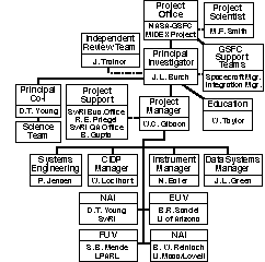
4.1.1 Project Organization. The project organization chart is shown in Figure 4.1.1. The P.I. will be assisted by a Project Manager (PM) and a small group of experienced engineers and scientists in the day-to-day management of the IMAGE program. A single instrument manager will serve as the coordinator for all instrument development activities. The instrument manager also has a single point of contact within each institution building instrument hardware (see Table 4.1.1). Likewise, a single individual will coordinate all co-investigator activities. The IMAGE management team will include an Independent Review Team (see Figure 4.1.1) chaired by Dr. Jim Trainor, formerly Deputy Director of GSFC. The Independent Review Team will meet at regular intervals to review cost, schedule, and technical performance. By structuring our management team such that every critical activity has a single point of contact, we have streamlined our project operations, ensured quick and accurate communications, reduced management cost, and provided our team members with clear and simple lines of authority and communications.
With the exception of the funds flowing to co-I's at GSFC and MSFC, SwRI will provide funding to all U.S. IMAGE team members through subcontracts. Established subcontractor cost reporting (NASA 533) will be required from team members and will be submitted to GSFC. SwRI will be responsible for the technical and financial performance of all IMAGE team members.
For each funded team member, SwRI will develop a statement of work (SOW). In addition, the parameters of each instrument will be described in an instrument specification document (ISD), which will be updated throughout the project.
4.1.2 The IMAGE Decision-making Process. Activities will be coordinated with the PM and the PI through weekly management team meetings concerning the status of their activities, problem resolution, and resource allocation. We will submit informal reports to the MIDEX Project Office at the end of each of these weekly management team meetings. Resource usage will also be reviewed by the Independent Review Team.

Fig. 4.1.1. IMAGE organizational chart.
We will establish a strong systems engineering activity, which will encompass instrument and spacecraft technical issues. Systems trade studies will be managed with the goal of obtaining the best science within contract resource limitations. The PI will be responsible for making final decisions relating to the results of trade studies. Close coordination with the spacecraft team members will be maintained throughout the systems engineering process.
4.1.3 Team Organization and Responsibilities. Table 4.1.1 contains a list of IMAGE team primary institutions that will carry the responsibility for the development of the flight hardware and software. Each team member is experienced and equipped to carry out the hardware development responsibilities. The infrastructure exists at each institution to support the performance assurance, fabrication, integration, functional and environmental testing, and personnel training necessary to insure high reliability flight equipment.
SwRI will work with GSFC Performance Assurance (PA) engineers to develop an IMAGE PA Requirements document. We will then work with the individual team members to develop PA implementation plans. The team members will each be required to establish and implement a Configuration Mgt. (CM) plan. Each team member will be subject to a CM audit. For Configuration Control Board (CCB) action, each team member will be granted authority for class II configuration changes. Class I changes will be coordinated with GSFC by SwRI. Interfaces between an instrument and the spacecraft or the CIDP will be documented as a part of the instrument specification document. SwRI will be responsible for strict enforcement of interface configuration control between the payload and the spacecraft.
| Institution | Responsibilities | Point of Contact | Related Experience |
|---|---|---|---|
| SwRI | PI institution, project management, MENA and CIDP development, RPI flight electronics packaging, integrated systems test |
J.L. Burch (PI) W.C. Gibson (PM) D.T. Young (NAI Team Leader, Co-I) |
UARS/PEM ATLAS/SEPAC Cassini/CAPS DE/HAPI/LAPI Polar/TIDE |
| GSFC | LENA development Ground data systems | M. Smith, J. Green | AMPTE/UKS,CRRES DE, GGS, NSSDC |
| U. of Maryland | HENA development | D. Hamilton | AMPTE/CHEM |
| U. of Arizona | EUV development | B. Sandel | Viking |
| LPARL | FUV development | S. Mende | ATLAS/AEPI,Polar/TIMAS DE, ISEE |
| U. of Mass-Lowell | RPI design, flight RPI integration and test | B. Reinisch | DPS |
4.1.4 Risk Management. Throughout the IMAGE development program we will apply the classic elements of risk management: identification, avoidance, and control. Although we generally associate risk control with the use of unproven technologies, it can include schedule, cost control, or instrument performance risk. Our approach to risk is based on early identification of technical risk areas during Phase I. The only new technologies involved in IMAGE are the cesiated-surface neutral-atom ionization technique (LENA) and the multilayer mirrors (EUV). Laboratory work has been in progress for some time at the Universities of Bern and Arizona on these technologies, and we are confident that any risk associated with them will be effectively mitigated. Through careful attention to cost and schedule performance, we will control our resource management risks.
4.2 IMAGE SCHEDULE AND SCHEDULING SYSTEM
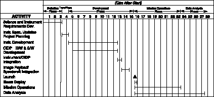
Figure 4.2.1 shows a top-level development schedule for the IMAGE investigation. Each of the instrument managers will be responsible for maintaining detailed schedules for their respective activities. The PM will integrate each of these individual schedules into a master IMAGE schedule. This will be done using Microsoft's Project software package. Each instrument manager's schedule becomes a subproject to the IMAGE master schedule. Each month our team members will transfer their updated PROJECT files over Internet to SwRI. The SwRI PM will then integrate the team supplied subproject schedules to form a master project schedule. Not only will the process just described produce a complete and accurate schedule, but it will also highlight resource conflicts. The scheduling process will be performed at least once per month. Copies of our updated schedules, showing actual vs. planned schedule performance, will be made available to the MIDEX project office.

Fig. 4.2.1 IMAGE top-level schedule.
4.2.1 Long Lead Items. Long lead items include mirror coating and curved MCPs (EUV), mirror system (FUV), antenna deployment mechanisms (RPI), and rad hard parts. Some of these parts may need to be purchased at start of the development phase.
4.2.2 Critical Path. Critical path items include the cesiated surface (LENA), the FUV MCP/diode array, and the HENA detectors.